
Guidance for YASA ET S-EC Electrocoagulation Lab Kit Setup
- Feb 7
- 12 min read
Updated: Mar 4
Introduction
1.1 Electrocoagulation Lab Test Kit Overview
The YASA ET PREDEST® EC Test Kit is a professional-grade, portable laboratory system designed for the evaluation of Electrocoagulation (EC) and Electro-oxidation (EO) performance. It is an essential tool for research and development (R&D) teams, universities, and environmental engineers to conduct treatability studies on various industrial and YASA ET ECEO Labkit setup(municipal wastewaters.
The kit allows users to determine the optimal treatment parameters, such as current density, voltage, and reaction time, required to scale up to full-capacity treatment plants while saving time and avoiding costly mistakes.
1.2 Electrocoagulation Working Principle
Electrocoagulation is an electrochemical process that uses an electrical charge to destabilize and coagulate contaminants without the heavy use of external chemicals.
Electrolytic Reaction:
A direct current (DC) is passed through sacrificial metal electrodes (typically Iron or Aluminum) submerged in the wastewater.
Cation Release:
The anode undergoes oxidation, releasing metal cations (Fen+ or Al3+) into the water.
Contaminant Removal:
These cations act as coagulants, binding to pollutants to form stable, insoluble flocs. Simultaneously, gas bubbles (Hydrogen) produced at the cathode promote Electro-flotation, carrying lighter flocs to the surface for easy removal.

1.3 Electrocoagulation Lab Test Equipment Key Applications
The PREDEST® S-EC Kit is highly effective at removing a wide range of pollutants, including:
Heavy Metals: Chrome, Nickel, Copper, etc.
Organic Matter: Reduction of COD and BOD.
Oils and Fats: Breaking of emulsions and removal of oil & grease.
Suspended Solids: Total Suspended Solids (TSS) and turbidity reduction.
Specialized Contaminants: Fluoride, calcium/magnesium ions, and colour.
1.4 Technical Specifications
The standard kit is available in multiple configurations (1L, 5L, 10L) to suit different testing scales.
Component | Specification |
Reactor Material | Transparent, corrosion-resistant Acrylic (Acrylate) |
DC Power Supply | 0–24V / 0–30A (adjustable) |
Standard Electrodes | 4–5 pairs of Aluminum and Iron plates |
Plate Dimensions | 123 × 100 mm (3 mm thickness) |
Flow Rate | Adjustable 40–160 L/h |
Optional Electrodes | Titanium, BDD, Graphene, Stainless Steel, etc. |
General Safety Commands
Safety is the highest priority when operating the EC Test Kit. Failure to follow these instructions may result in personal injury, environmental damage, or equipment failure.
2.1 Personal Protective Equipment (PPE)
Always wear the following prescribed PPE when operating the equipment or handling wastewater:
Safety Goggles: To protect eyes from chemical splashes and accidental contact with wastewater.
Chemical-Resistant Gloves: (e.g., Nitrile or Neoprene) to prevent skin contact with hazardous substances or treated effluent.
Protective Clothing: Lab coats or aprons to protect against spills.
Masks: Use respiratory protection if the wastewater emits hazardous vapors or if fine particulate matter is present.
2.2 Electrical Safety
Knowledge Requirement: Only personnel with basic knowledge of safe electricity use should operate the DC power supply.
Dry Hands & Surface: Ensure your hands and the operating surface are completely dry before touching any electrical controls.
Connection Order: Always verify that the power supply is OFF before connecting or disconnecting the electrode cables (positive/negative wires).
Avoid Short Circuits: Never allow the positive and negative electrode plates or cables to touch while the power is on.
2.3 Chemical & Wastewater Handling
Review SDS: Before starting any test, read the Safety Data Sheets (SDS) for any chemicals used (e.g., for pH adjustment or conductivity enhancement).
Pre-neutralization: The device is not suitable for highly acidic or alkaline environments; wastewater must be pre-neutralized to a safe range before treatment.
Ventilation: Operate the kit in a well-ventilated area or under a fume hood. Electrocoagulation produces small amounts of gas (hydrogen and oxygen), which must be safely dispersed.
Spill Response: Maintain anti-leakage measures and water washing devices nearby in case of accidental chemical release.
2.4 Environmental & Operational Constraints
Temperature Range: Maintain wastewater temperature between 5°C and 45°C.
Low Temp (<5°C): Risk of freezing and equipment damage.
High Temp (>45°C): Risk of overheating electrical components and compromising reactor integrity.
Hazardous Waste: All generated waste (sludge and treated water) must be disposed of through a qualified disposal unit in accordance with local environmental regulations.
2.5 Equipment Integrity
No Unauthorized Mods: Use only original YASA ET spare parts. Unauthorized changes to equipment parameters can lead to system failure.
Leak Check: Always perform a leak check with tap water before introducing wastewater into the system
Hardware Setup: Reactor Assembly
This section covers the physical preparation of the PREDEST-EC/EO Test Tank. Proper plate placement and connection are critical for ensuring uniform current distribution and effective treatment.
3.1 Positioning the Equipment
Before assembly, place the Pump Housing (Skid) and the Test Reactor (Tank) on a flat, stable, and dry laboratory bench.
Maintain a distance of at least 20 cm between the pump housing and the test tank to allow for easy tubing management and safety.
3.2 Main Power Wire Installation (AC Input)
Before the DC power supply can be used, the main power cord must be attached to the unit. Follow this specific sequence to prevent accidental electric shock. Voltage Verification.
Before plugging in the device, check the back of the DC power supply for the Voltage Selector Switch.
⚠️ Safety Command: No Live Connections
NEVER connect the wires to the power supply if the other end of the cord is already plugged into a wall socket. The wire terminals are exposed during this process, and touching them while "live" will result in a severe electric shock.
3.2.1 Step-by-Step Installation Sequence
Inspect the Cord: Ensure the AC power cable is unplugged and the wires at the "open end" are clean and not frayed.
Verify the Voltage Switch: Check the back of the power supply and ensure the voltage toggle (110V or 220V) matches your local power grid before proceeding.
Identify the Terminals: On the back of the power supply, identify the three input terminals:
L Blue wire.
N: Brown wire.
G: yellow-green wire.
Secure the Wires: Loosen the terminal screws on the power supply.
- Insert the wires into their respective slots (L, N, and G).
- Tighten the screws firmly. Give each wire a gentle "tug" to ensure it is locked in place.

Install the Terminal Cover: Most YASA ET power supplies include a transparent plastic cover. Snap this into place over the terminals to prevent accidental contact.
3.2.2 Final Verification Before Plugging In
Only after the wires are securely fastened to the power supply and the terminal cover is on should you proceed to the next step:
Step A: Confirm the power switch on the front of the unit is in the OFF (O) position.
Step B: Now, and only now, insert the plug into the wall electric socket.
Operator Note: If you see any sparks or hear a "pop" when plugging the unit in, immediately disconnect it and check your terminal connections for a short circuit.
3.3 Electrocoagulation Electrode Plate Installation
The PREDEST system uses a series of metal plates as sacrificial anodes and cathodes.
Select Your Plates: Choose the appropriate material for your test (typically Aluminum or Iron). Ensure plates are clean and free of heavy oxidation or grease before insertion.

Insert into Slots: Carefully slide the metal plates into the designated vertical slots within the acrylic reactor box.

The Alternating Physical Sequence
When sliding the plates into the reactor slots, you must alternate the materials (or the intended charge) to create a "sandwich" effect.
Slot 1: Positive Plate (Anode)
Slot 2: Negative Plate (Cathode)
Slot 3: Positive Plate (Anode)
Slot 4: Negative Plate (Cathode)
Placement: Ensure they are seated securely at the bottom of the slot to prevent shifting during water circulation.
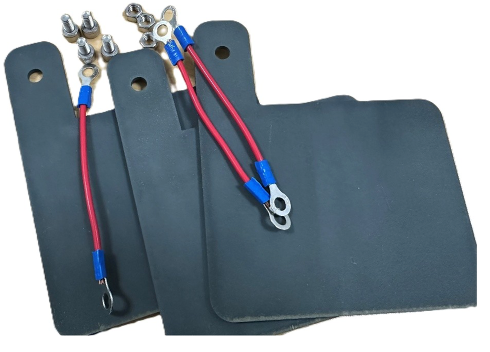
Terminal Bolts: Locate the Terminal Blocks and M6 Terminal Bolts provided in the accessories kit.
Mount the terminal blocks to the sides of the reactor to provide a secure contact point for the electrical wires.
3.4 DC Wiring: Connecting Plates to Power Supply
Once the electrode plates are physically installed in the reactor slots, they must be electrically energized.
On the exterior of the acrylic reactor, you will find two sets of M6 Terminal Bolts and Terminal Blocks. These serve as the "bridge" between the internal plates and the external power source.
-> Anode Side (+): Connected to the sacrificial plates (e.g., Iron or Aluminum).
-> Cathode Side (-): Connected to the counter-electrodes.
3.4.1 Internal Wiring (Plates to Terminal)
After the plates are physically in place, they must be wired so that all plates of the same charge act as one unit.
Positive Grouping: Using the provided 1.5 $mm^2$ wires, connect all the Positive plates (plates 1, 3, 5...) to each other in a series/chain. Connect the end of this chain to the Red (+) Terminal on the power supply.
Negative Grouping: Connect all the Negative plates (plates 2, 4, 6...) to each other in a series/chain. Connect the end of this chain to the Black (-) Terminal on the power supply.

3.4.2 Visual Confirmation
Before proceeding, look at the top of the reactor. It should look like this:
1. Red Wire → Plate 1 → (jumper) → Plate 3 → (jumper) → Plate 5.
2. Black Wire → Plate 2 → (jumper) → Plate 4 → (jumper) → Plate 6.
⚠️ Critical Check: Ensure that a "Positive" wire never touches a "Negative" wire or plate. If they touch, it will cause a short circuit and may damage the DC Power Supply.

Fluid Path & Tubing Installation
Now that the electrical system is ready, we must connect the plumbing to allow the wastewater to circulate through the plates.
4.1 Connecting the Ø10 Water Pipes
Before attaching the blue Ø10 water pipes, you must install the G1/8 valves into the pre-drilled ports on the reactor tank. These valves act as the gateways for your liquid samples.
4.1.1 Identifying the Inlet and Outlet
The Inlet (Electrode Side): The port located on the side of the tank containing the electrode plates is the Inlet. Water enters here to ensure it immediately comes into contact with the sacrificial anodes and cathodes.
The Outlet (Empty Side): The port on the opposite side, where the water has already passed through the plates, is the Outlet.
4.1.2 Installing the G1/8 Valves

Check Seals: Ensure the O-rings are seated correctly on the valve threads to prevent leaking.
Mounting: Hand-tighten one valve into the Inlet port (plate side) and the second valve into the Outlet port (opposite side).

Final Tightening: Use a wrench to tighten the valves by an additional 1/4 turn.
Warning: Do not over-tighten, as the acrylic material is prone to cracking under excessive torque.

4.2 Fluid Path & Tubing Installation
With the valves in place, you can now connect the plumbing to create a circulation loop.
4.2.1 Connecting the Pipes
Suction Line: Connect a pipe from your Wastewater Source Tank to the Inlet of the pump on the skid. Or you can just connect the outlet from the reactor to the inlet of the pump.

Feed Line: Connect a pipe from the Pump Outlet to the Inlet Valve (plate side) on the reactor.
Return Line: Connect a pipe from the Outlet Valve (empty side) back to your collection tank or source tank, or you can just connect it back to the inlet of the pump.

4.2.2 Securing the Connections
Insert: Push the pipe firmly into the valve’s quick-connector until it stops. You should feel it lock into place.
Test: Give the pipe a gentle tug to ensure it is secure.
Release: To remove a pipe, push the plastic collar of the connector inward while pulling the pipe out.
Connecting the Pump to the Power Source
The pump skid has its own power connection separate from the DC power supply used for the plates.
--> Check Voltage Requirements: Verify if your pump skid is rated for 110V or 220V AC.

--> Cable Connection: Take the AC power cord from the pump skid and connect it to your main electrical source (wall socket or the power strip on your lab bench).
5.1 Connecting the Power Adapter
Plug the DC connector (the small round tip) of the power adapter into the power input port on the Pump Skid.
Ensure the dial on the adapter is turned all the way to the "Min" or "Off" position before plugging it into the wall.
Plug the AC plug into a standard grounded wall outlet.
5.1.1 Adjusting the Flow Rate
Once the power is connected and the reactor valves are open, you can begin circulation:
Start Circulation: Slowly turn the dial on the power adapter clockwise. You will hear the pump start and see the liquid begin to move through the pipes.
Calibrate Flow: Increase Flow: Turn the dial toward the maximum setting to speed up the circulation. This is useful for rapid mixing or flushing the system.
Decrease Flow: Turn the dial toward the minimum setting. A slower flow is often better for Electrocoagulation as it allows the wastewater more "residence time" between the electrified plates.
Visual Verification: Observe the reactor tank. The flow should be steady enough to keep the water moving without causing excessive splashing or overflowing the outlet.

Starting the Electrocoagulation Process
Once the hardware is assembled and the power is connected, you can begin the treatment. There are two primary methods for filling the reactor tank, depending on your testing requirements.
6.1 Filling the Reactor (Two Methods)
Method A: Manual Direct Pour (Batch Mode)
This is the simplest method for quick tests or when you have a specific fixed volume of wastewater.
Ensure the Inlet and Outlet valves are closed.
Slowly pour the wastewater directly into the top of the acrylic reactor tank.
Fill until the water level fully covers the electrode plates but remains below the top rim to avoid splashing.

Method B: Pump-Assisted Filling (Recirculation Mode)
Use this method for continuous flow or when mixing a large source tank.
Place the suction pipe into your external wastewater container.
Open both the Inlet and Outlet valves on the reactor.
Turn the dial on the Pump Power Adapter clockwise to start the pump.
Allow the pump to fill the reactor. Once the water reaches the outlet port, it will begin to circulate back to your source tank.
6.2 Powering the Reaction
Main Power: Flip the power switch on the front of the DC Power Supply to the ON position.
Adjusting Voltage & Current: * Slowly turn the Voltage (V) knob. You will see the voltage rise on the digital display.
As the voltage increases, the Current (A) will also begin to rise.
Target Setting: Adjust until you reach your calculated current density (Amps) required for the specific wastewater type.

6.3 Observations During Operation
As soon as the current begins to flow, the electrochemical process starts. Monitor the following:
Gas Evolution: You will see tiny bubbles (Hydrogen and Oxygen) forming at the surface of the plates. This is normal and helps float pollutants to the top (Electro-flotation).
Color Change: Depending on the electrodes used (Iron will turn the water greenish/brownish; Aluminum will create white/cloudy flocs), the water color will shift as metal ions are released.
Floc Formation: Contaminants will begin to clump together into "flocs."
Heat Check: Periodically check the terminal bolts and wires. They should be warm but never hot. If they are hot, turn off the power and tighten the connections.
Sampling
Use a beaker or a syringe to collect water samples from the Outlet Valve at specific time intervals (e.g., 5, 10, 15 minutes) to track the treatment efficiency over time.
Shutdown, Cleaning, and Maintenance
Proper shutdown and cleaning are essential to prevent electrode passivation (the buildup of an insulating layer on the plates), which can reduce the efficiency of future tests.
8.1 Shutdown Sequence
Turn off the DC Power Supply: Rotate the voltage/current knobs to zero and flip the main power switch to the OFF position.
Turn off the Pump: Rotate the dial on the pump power adapter to the Min/Off position.
Close the Valves: Turn the Inlet and Outlet valve handles to the perpendicular (closed) position.
Disconnect Wires: Unplug the Red and Black cables from the reactor terminals to prevent any accidental short circuits during cleaning.
8.2 Draining and Cleaning the Reactor
Drain the Liquid: Open the outlet valve (or use the pump) to move the treated wastewater and sludge into a waste container.
Rinse: Fill the tank with clean tap water and run the pump for 2–3 minutes to flush the pipes and the reactor body.
Plate Removal: Carefully slide the electrode plates out of their slots.
Mechanical Cleaning: Use a plastic brush or a mild abrasive pad to scrub the surfaces of the plates. This removes the "scale" or oxidation layer that forms during the EC process.
Note: If the plates are heavily scaled, a brief dip in a weak acid solution (like 5% Citric Acid) can help restore the metal surface.
Dry: Wipe the plates and the interior of the acrylic tank with a soft cloth.
8.3 Maintenance & Long-term Storage
Plate Replacement: Check the thickness of your sacrificial anodes (Iron/Aluminum). If they have become significantly thinner or "pitted," replace them with new plates from your YASA ET spare parts kit.
Seal Inspection: Regularly check the O-rings on the G1/8 valves for cracks.
Storage: If the kit will not be used for more than 15 days, ensure all components are completely dry and stored in a dust-free environment.
Symptom | Possible Cause | Solution |
No Current (0A) on Display | Broken wire or loose terminal | Check all connections from the power supply to the plates. |
Voltage is high, but Amps are low | Low water conductivity | Add a small amount of NaCl (table salt) to the wastewater. |
The pump is running, but no flow | Air lock or closed valve | Ensure both valves are open and pipes are submerged. |
The acrylic tank is leaking | Loose valve or cracked port | Tighten G1/8 valves slightly or check O-rings. |
8.4 Disposal Instructions
Sludge: The "flocs" collected during the test may contain concentrated pollutants or heavy metals. Dispose of this sludge according to local hazardous waste regulations.
Electrodes: Used and thinned metal plates should be recycled as scrap metal.
For the right treatment system, you need the right expertise.
For more information about our zero liquid discharge systems, kindly get in touch at:
🌐 www.yasa.ltd(EN)
🌐 www.yashahuanjing.cn (中文)
📱 +86 136 3643 1077
YASA ET official online store > click here


Comments